
Optical fibers are thin waveguides made of glass and are used for transportation of light. Widely used in the telecommunication industry, in the 1980s they started to be used in astronomy to couple light from the telescope focus to highly specialized and sophisticated instruments located elsewhere, eg. in the observatory basement (Heacox 1986).
Fibers typically have three layers, the core, cladding and buffer (Figure 1).Fibers and operate on the principle of total internal reflection (TIR) : the core and cladding are made from glass, and the refractive index of the core is higher than that of the cladding to enable TIR. The role of the buffer, on the other hand, is to provide protection to these fragile glass strands.
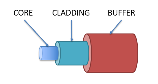
Figure 1 : Optical fiber layout
For an extreme RV precision instrument like NEID, optical fibers offer various advantages, some of these are : –
- By decoupling the instrument from the telescope focus, they allow for the instrument to be quite heavy and sophisticated (NEID weighs about a couple metric tons!) . Further, it allows the instrument to be housed in the basement of the WIYN telescope in a room with temperature control to the level of 1 degree Celsius or better.
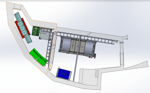
Figure 2 : WIYN basement showing the location of NEID, the laser frequency comb and the electronics rack/s.
- Having the instrument in the basement also means a near constant gravitational vector for the instrument. An instrument at the Cassegrain focus of the telescope would move constantly as the telescope tracks the target. This is important to prevent a variable sag or bending of the optics or mounts in the instrument.
- The fiber provides a degree of scrambling for the light. This means that illumination at the output end of the fiber is less sensitive to the the location of the star on the input face. This is important to average over any illumination changes or guiding errors of the telescope (See Halverson & Roy et al. 2015).

NEID Fiber Train
Shown below is the entire fiber train for NEID. Here, we shall go over some of the components.
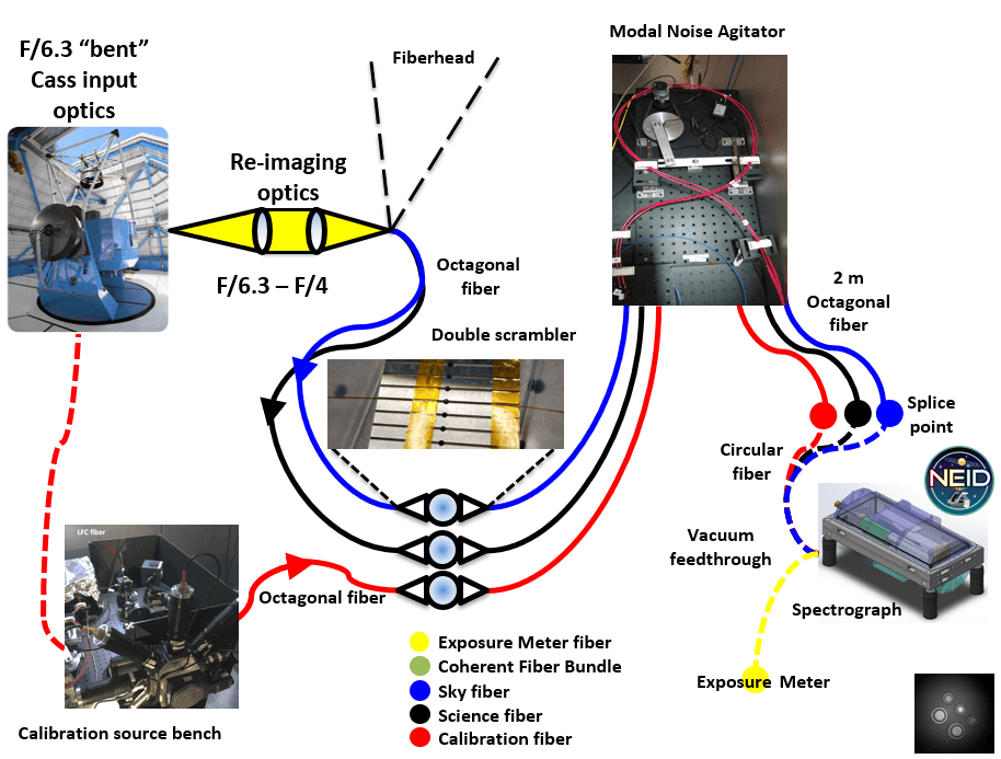
Figure 3 : Overview of the NEID fiber train
Fiber puck and polishing
NEID has two different operating modes, High Resolution (HR) for the brighter targets for maximum RV precision, and High Efficiency (HE) for the fainter targets, with higher throughput. To enable this, the HR mode has smaller fibers (64 micron core) while the HE mode fibers are bigger with ~100 micron cores to allow for higher efficiency.
For the HR mode we have three fibers – Sky, Science and Calibration ; whereas the HE mode has only Science and Sky (bigger fibers take up more detector real estate). The Science fiber, of course, is where the stellar light enters the instrument. The Calibration fiber in the HR mode is used for simultaneous wavelength calibration of the stellar spectrum. The Sky fiber is used for a variety of telluric corrections.
This combination of HE and HR mode fibers are inserted into a fused silica puck manufactured by Femtoprint using a combination of a femtosecond laser and hydrogen fluoride etching. This is shown in Figure 4.
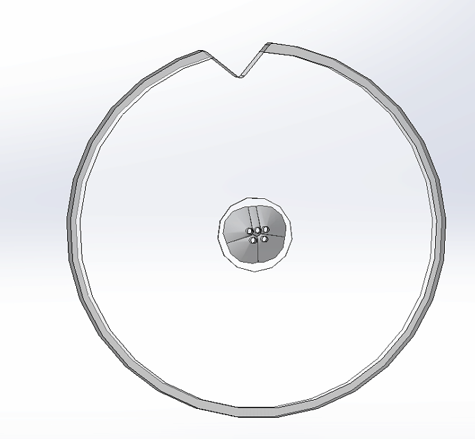
Figure 4 : F. Silica puck from Femtoprint. It shows the 5 bore holes for the 3 HR and 2 HE fibers, along with their conical inserts to ease the process of fiber insertion.
After inserting the fibers in the puck they are epoxi-ed into place using Epotek 301 – 2; once this epoxy dries, we polish the puck. For the polishing we use a custom made polishing jig which attaches the puck shown above to the polishing arm on the table. It then moves in a ‘figure of 8’ pattern to polish the fiber. To do this we start with a coarse 60 um grit, and progressively move to smoother grits as 12, 5, 3, 1, 0.3 um grits of silicon carbide, aluminium oxide and diamond.
Figure 5 : Video clip showing the polishing mechanism
Once we polish the puck, and grind away all the epoxy, the resultant puck looks like shown below in Figure 6. We need to get a good surface smoothness to prevent FRD deterioration from roughness on the end surface of the fiber.
Further for NEID we plan to stick a plano – convex lens onto this polished puck surface as part of the input optics focal ratio changer, and to protect the fiber surface from damage.

Figure 6 : Polished NEID puck
Fiber Splicing
The fiber that goes inside the instrument in this puck is circular. However, the rest of the fiber train is octagonal. Therefore we splice the circular fiber on to the octagonal fiber face, which basically means fusing them together.
To do this, we first strip away the polyimide buffer shown in Figure 1. We do this using a 3SAE plasma arc fiber stripper. This creates a plasma arc between three electrodes located 120 degrees apart. The fiber is placed between them and slowly gets stripped off of its buffer. Shown in Figure 7 is the fiber being stripper for the HPF fiber.
Figure 7 : Clip showing an HPF fiber being stripped
After this we use a diamond blade cleaver to cleave (cut) the stripped fiber. The stripped fiber has about a 4 -5 mm patch of exposed fiber (only core and cladding). This is then spliced on to the patch of fiber using a device similar to the stripper – it uses three electrodes to create a plasma arc which fuses the two ends together. Below in Figure 8 is shown a test fiber after being spliced. Figure 9 shows the spliced HPF fibers in a splice sleeve and heat shrink tubing to protect the splice.

Figure 8 : Splice test for NEID fibers
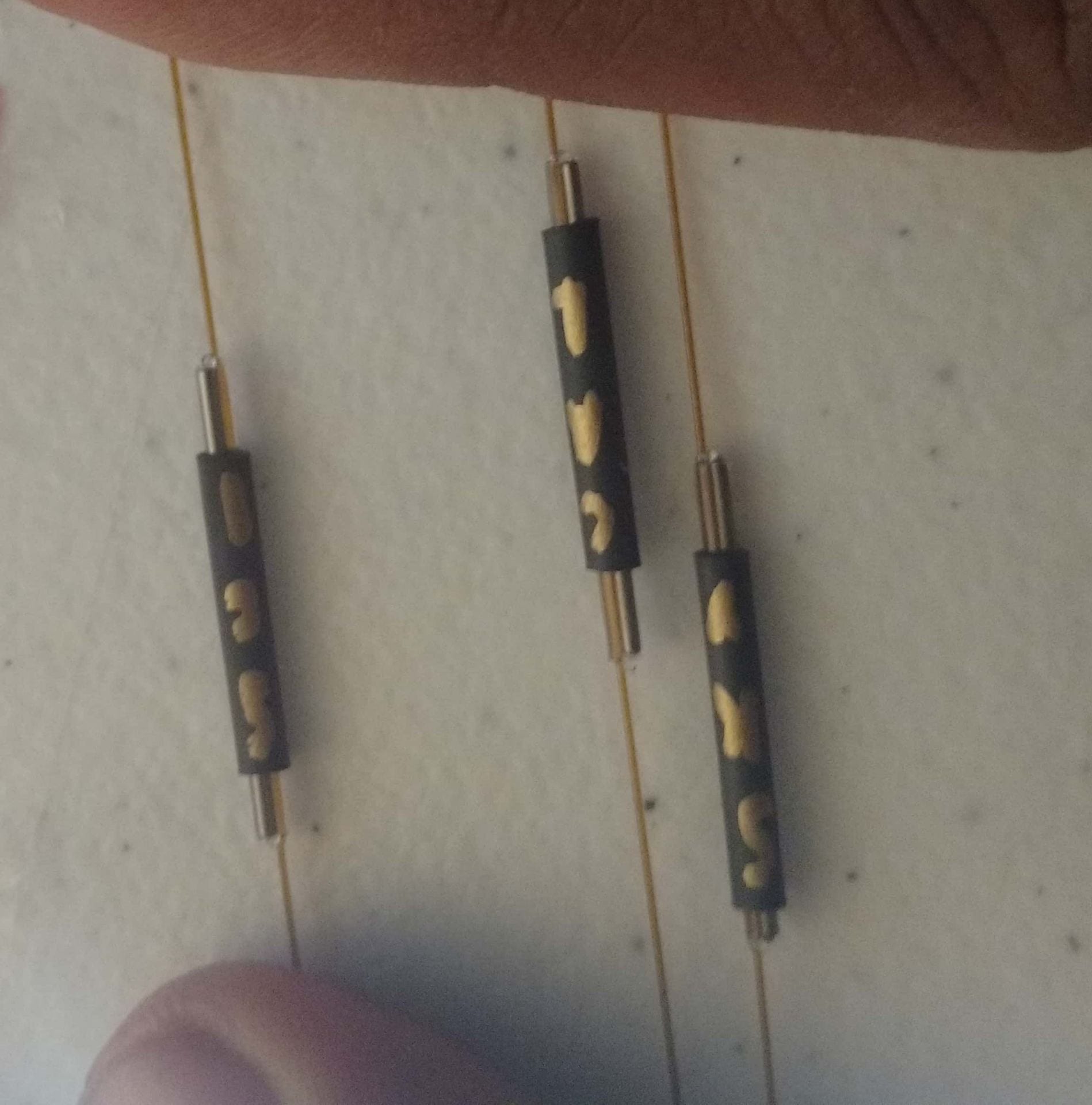
Figure 9 : Splice protection for the HPF fibers. NEID fibers will be similar
Modal Noise Agitator
The optical fibers being used for HPF and NEID are multi-mode, and hence support a finite number of modes. Hence the light emerging from the fiber contains an interference pattern between the many modes traversing across the fiber. This is called modal noise, or “speckle noise”. For big fibers, there are enough modes that the statistical variation in the change in energy distribution of modes is insignificant. However, in the presence of smaller fibers as in NEID, or the use of slits or fiber slicing, modal noise needs to be mitigated for the measurement of precise radial velocities.
The HPF science and sky fibers are agitated using the device shown below; whereas for the calibration fiber we use a combination of a mechanical agitator and an integrating sphere. This is because the problem gets exacerbated for the calibration fiber which uses the laser frequency comb – a highly coherent light source.
For an introduction to understand Modal Noise, refer to – Baudrand and Walker 2001, McCoy et al. 2012, Mahadevan et al. 2014.
Figure 10 : Clip showing the fiber agitator for HPF. NEID will use a similar one.
Double Scrambler – Ball Lens
Fibers provide some degree of scrambling the spatial location of the input spot (Heacox 1986), however for precision RV application, this needs to be improved by many orders of magnitude. For HPF and NEID we use the ball lens described in Halverson & Roy et al. 2015. Basically, our scrambler is a simple ball lens with refractive index ~ 2, which exchanges the far and near field of the fiber. The two ends of the fibers are placed inside a v – groove block (as shown in Figure 11), and butt coupled to the ball lens which is in the middle.
This ball lens is based on the double scrambler concept proposed early in the days of fiber-fed spectroscopy by Hunter and Ramsey (1992) at Penn State!
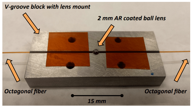
Figure 11 : Showing the ball lens setup during prototyping. Figure Credit : Halverson 2015
Figure 12 shows how the scrambling performance improves for an octagonal fiber over a circular, further the gains for the double scrambler, and for the spliced system.
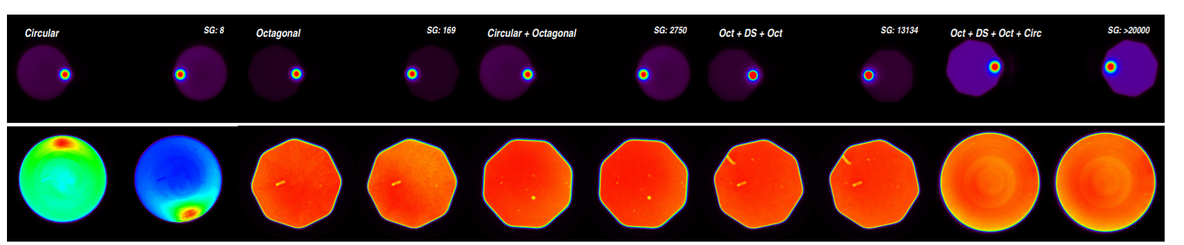
Figure 12 : Showing the scrambling gain.
The top panel shows the input face of the test fiber. Whereas the bottom one shows the near field. Figure Credit : Halverson 2015.
This entire system forms the instrument optical fiber package. There are some additional systems involved for the acquisition camera as well as the exposure meter, which are not discussed here. Essential to ‘carry’ the photons from the telescope or calibration sources into the instrument, the fibers are like the circulatory system of the instrument! (In this analogy, the electronic system is perhaps the nervous system, communicating information from the sensors and heater to the system computer.)